Lots of prosecutors and police scientists like to present the Gas Chromatograph (GC) and its results as totally infallible, not subject to interpretation, and never wrong.
While GC technology is good (in fact if the analysis is conducted on a stable and properly maintained and installed instrument using a validated method with a well-trained and well-educated true scientist operating it is perhaps the best qualitative device available to us now), it is not anything more than a machine. A fancy machine, but still a machine.
Like all machines, it breaks down.
Like all machines, it requires preventive maintenance periodically.
Like all machines, it should be very strictly monitored to insure that it is producing correct (valid) results.
There is a myth that I see in court and in transcript after transcript that this machine, the GC, regulates and monitors itself and if anything with this machine “goes wrong,” it will not produce a result.
Horse hockey.
Pure horse hockey.
Just as your car will keep driving along even if you ignore the need for oil changes, this machine, the GC, will keep on spitting out results even if not properly maintained. Notice I wrote that it would produce results, but not that it would produce the correct (valid) results. There is a big difference between the two.
Just as your car will keep driving on bald tires but it may not get you safely where you want to go on a rainy day, this machine, the GC will keep on spitting out results even if the directions for best use are not followed. Notice I wrote that it would produce results, but not that it would produce the correct (valid) results. There is a big difference between the two.
There is a difference between what could be done, what should be done and what is done during preventive maintenance of a GC. The bottom line is that your laboratory should have a written policy procedures and instructions as far as what must be done and what triggers it. It should always be a data driven decision.
The best way to look at it is from a system point-of-view. Remember this whole device is a wonderfully complicated interaction of various parts that must come together perfectly to get a valid result.
- I would start by looking at the Gas Cylinders. It is something that is taken for granted, and by no means is a given. I took a tour of AirGas and it was fascinating. An important concept is not simply the gas purity as delivered to the cylinder, but also the “born on date” of the cylinder itself. You can read about this important concept and potential source of contamination here. Born on Date– Not Just for Beer But Gas Cylinders Too
- Next I would look at whether or not there is a gas purification system in place that is between the cylinder and the instrument.
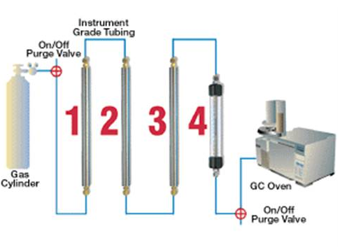
There are different types and performance characteristics of these gas purifiers (e.g., moisture purifiers to remove H2O, hydrocarbon traps that remove volatile organic compounds, and oxygen scrubbers to remove oxygen). The four shown consist of four gas purifiers to remove moisture, contaminating organic substances (VOCs) and oxygen. All of those can contribute to a “bad result.”
As shown above this system is configured as containing:
High Capacity Moisture trap
High Capacity Hydrocarbon Trap
High Capacity Oxygen Trap
Back-up Indicating Oxygen Trap
3. Next, I would move on and look at the injector port.
There are many different parts of the injector port. It is the septum, the inlet liner, the O-ring, and the golden seal that make up the injector port consumables. These are the consumable portions (just in the injector port) that must be replaced periodically to insure reproducibility and robustness in the GC. There is no hard and fast “must replace by” time for these items as determined by the manufacturer or validated in a scientific sense. Agilent recommends (key word) monthly replacement of these items for Volatile Organic Compound (VOCs) sampled by headspace, which is what we usually do. If a lab has such a procedure it is out of the abundance of caution not because the manufacturer says you must to do so.
The wear on these consumables depends upon the use of the GC (volume of throughput) and the matrix influenced. If it is direct liquid injection, then these consumables will have to be replaced a lot more frequently than with headspace. If it is not direct injection and if the instrument, it is seeking to sample only VOCs and the method always calls for headspace analysis (i.e., it is a dedicated machine) then these items do not need to be replaced as frequently. They do need to be replaced. Generally in industry there is a Good Laboratory Practice instruction that is set up with some sort of replacement schedule. That being said we, in the forensic science arena, are in the non-regulated world (as opposed to EPA or FDA) and therefore what I most see with labs all across the US they either have some sort of replacement schedule (which is very rare) or when they see abnormal results, then they consult with the manufacturer who teaches them the importance of these consumables.
The function of the inlet liner is to act as a last place of resort to trap any “junk” that would be introduced onto the column and also to allow for homogenized distribution of the vapor to reduce random sampling error. The primary purpose of the golden seal is to seal the inlet to help maintain the chromatographic conditions and also provide for uniformity in the distribution of the vapor in the inlet. It is housed within the injector portion of the instrument.
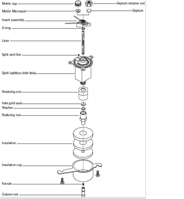
Figure 1 above: a labeling of the injector port housing

Figure 2 above: The new inlet liner with O-ring (N.B., there are also many different types and configurations of inlet liners that can affect the performance of the instrument and the validity of the result both in terms of the qualitative measure and the quantitative measure of that qualitative measure.)
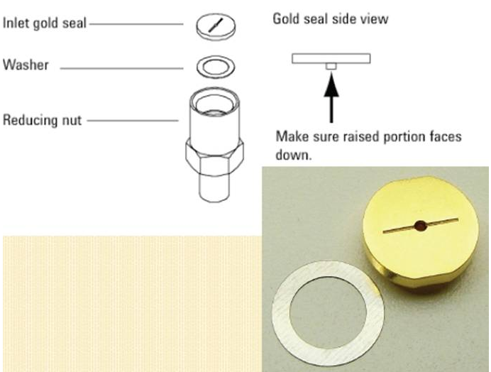
Figure 3 above: Exploded view of the reducing nut housing at the bottom of the injector port housing and a close up of the gold seal
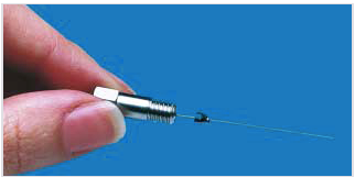
Figure 4 above: a graphite ferral.
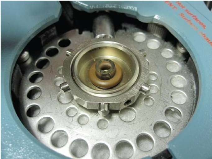
Figure 5 above: a picture of an installed inlet liner
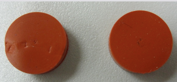
Figure 6 above: 2 used septa
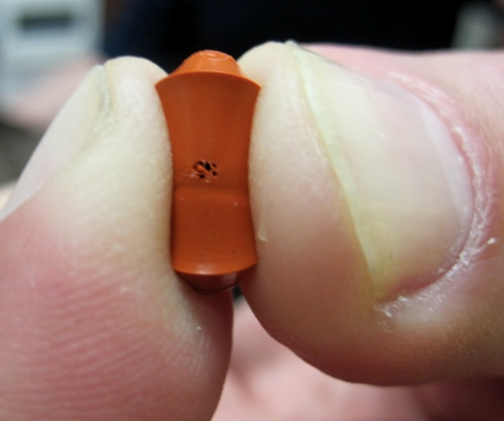
Figure 7 above: an easy way to check the integrity of a septum
Video 1 above: Video that I took while disassembling an GC injector port
Video 2 above: A video I took of disassembling a FID
Video 3: A good video of the process of removing and installing various consumables from the oven side.
Video 4: A good video of the process of removing and installing various consumables on the injector side.
Video 5: Two good videoes of the process of removing and installing a column.
As an aside, in my opinion having done it about 60 times, properly installing a column and replacing all consumables properly where you get desired high efficiency is actually pretty tough to do. A lot of labs outsource the installation and changing of their GC columns and consumables to a third party service provider for this very reason.


